What Hidden Factors Secretly Undermine Your Industrial 3D Scan Data Accuracy?
Industrial 3D scan data accuracy is rarely lost because of one dramatic scanner failure. More often, small variables accumulate: a part is warmer than the calibration condition, a glossy region saturates the camera, vibration changes a projected pattern, the scanner is used near the edge of its working volume, or individually good scans are registered with a small systematic bias. The result can look clean in a CAD environment while carrying dimensional errors that matter during inspection, reverse engineering, tooling, or prototype validation.
The important distinction is between what a scanner can achieve under specified conditions and what a complete measurement workflow actually achieves on a particular part. ISO 10360-13 provides acceptance and reverification testing for optical 3D coordinate measuring systems, but its stated applicability includes cooperative surface characteristics. NIST research likewise emphasizes that real-world structured-light measurements can encounter error sources that are not fully represented by a single standardized artifact or nominal specification.
The hidden problem: accuracy is a system property
A 3D scanner does not measure geometry in isolation. The measurement chain includes the optical hardware, calibration state, target surface, illumination, environmental conditions, scanner-to-part geometry, tracking or registration method, point-cloud processing, and the reference used to judge the result.
That matters because an error introduced early can survive every later software operation. Filtering may make a noisy point cloud look cleaner, but it does not necessarily restore the true surface. Registration can create an apparently coherent model while distributing a systematic discrepancy across multiple scans. A mesh can be visually excellent and still fail a dimensional check.
NIST's work on structured-light scanners describes this broader problem explicitly: different systems can have different sensor configurations, projected patterns, working volumes, triangulation geometries, point densities, and target characteristics. A verification result therefore needs to be interpreted in the context of how the instrument will actually be used.
This is the first useful decision rule: if the production measurement conditions resemble the verification conditions, the verification result is directly informative; if they differ substantially, treat the published accuracy as a starting point rather than a complete uncertainty statement.
1. Temperature can move the geometry you think is stationary
Temperature is easy to underestimate because the scanner and the workpiece can both change. A scanner may contain cameras, lenses, projectors, mechanical frames, mounts, and other components whose dimensions or optical relationships vary with temperature. Meanwhile, the part itself can expand or contract.
A calibration performed in a stable laboratory therefore does not automatically describe a measurement taken beside a production line after a machine has warmed up. A peer-reviewed study of structured-light scanners investigated calibration quality across different temperatures using controlled thermal testing and reported measurable temperature effects. Other research has examined thermal deformation of scanner mechanical bases and projector components.
The practical issue is not simply “hot is bad.” What matters is the relationship between the temperature at calibration, the temperature during measurement, the thermal gradients within the equipment and part, and how long the system has been exposed to the new condition.
If the scanner and part are moving between significantly different thermal environments, document the temperatures and allow the system and workpiece to stabilize where the measurement procedure requires it. If the environment is already stable and tightly controlled, temperature may be a secondary contributor compared with surface reflectivity or registration.
2. Surface finish can change the measurement before geometry is reconstructed
Optical 3D systems depend on light reaching the sensor in a usable way. Glossy metal, polished coatings, transparent regions, dark finishes, oily areas, and surfaces with large reflectance variations can therefore produce very different measurement behavior from a diffuse, uniform surface.
High-reflectivity surfaces can generate saturated pixels, missing points, distorted pattern information, or unstable reconstruction. Peer-reviewed research on structured-light measurement has documented the difficulty of high-reflectivity metal surfaces, while other studies have shown that surface reflectance can materially influence scanner and calibrator measurements.
This is particularly important in reverse engineering because a visually simple part may be optically difficult. A polished aluminum housing, chrome component, black rubber seal, and painted steel bracket may all exist in the same assembly. The scanner is not receiving the same optical signal from each material even when the geometry is equally accessible.
If a surface produces saturation or large missing regions, address the optical condition before trusting the reconstructed geometry. Depending on the validated workflow, that may mean changing illumination or exposure, changing the scanning angle, using an appropriate removable matte treatment, or applying another documented surface-management method. If the surface is already cooperative, additional treatment can be unnecessary and may itself introduce contamination or thickness concerns.
3. Working distance and viewing angle are accuracy variables, not just convenience settings
Operators sometimes treat working distance as a framing decision: move closer for detail, farther away for coverage. In metrology, the geometry of the sensor relative to the object can also affect measurement performance.
Triangulation-based systems infer three-dimensional position from optical geometry. As the scanner moves toward the limits of its intended measurement volume, the available geometry, field of view, resolution, incidence angle, and feature visibility can change. Deep pockets and steep walls may introduce occlusion even when the exterior surface looks easy to capture.
The consequence is often subtle. A large part may scan successfully overall but contain local areas where point spacing, angle, or signal quality differs enough to affect a downstream dimensional feature. A nominally complete mesh does not prove that every region has equivalent measurement quality.
If a critical dimension lies near an occlusion boundary or at an extreme working distance, change the acquisition geometry before relying on post-processing to repair the data. If the feature is comfortably inside the validated working envelope, aggressive repositioning may add unnecessary registration steps.
4. Vibration and environmental light can quietly corrupt optical measurements
Precision scanning is sensitive to motion because the system assumes a defined spatial relationship while acquiring optical information. Mechanical vibration can come from nearby machine tools, conveyors, fans, building activity, operator contact, or the movement of the workpiece itself.
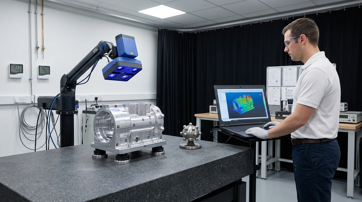
Environmental illumination is another hidden variable. Structured-light systems deliberately project known optical patterns, so uncontrolled external light can compete with the projected signal or change image contrast. NIST and VDI/VDE metrology guidance identify operating conditions such as temperature, humidity, mechanical vibration, electromagnetic interference, and environmental lighting as relevant considerations for optical 3D measurement.
The useful diagnostic distinction is between random noise and repeatable systematic change. If repeated scans fluctuate around the same geometry, averaging or robust processing may help characterize random variation. If every scan shifts in a similar direction under a particular condition, averaging can merely hide the systematic problem.
If repeated scans disagree unpredictably, investigate vibration, signal quality, and registration stability. If they agree with each other but disagree with a calibrated reference, investigate systematic error instead of simply increasing the number of scans.
5. Calibration can be valid and still be poorly matched to the task
Calibration establishes a relationship between what the sensor observes and the geometry it reports. It is foundational, but calibration is not a magic state that permanently guarantees accuracy in every configuration.
Changing lenses, sensor arrangements, measuring volume, projector settings, mounting conditions, or other configuration parameters can change the measurement chain. Some systems also depend on warm-up behavior or defined calibration procedures. A scanner that has been calibrated correctly can still be used incorrectly if the production configuration no longer matches the verified setup.
ISO 10360-13 is useful here because it formalizes acceptance and reverification concepts for optical 3D coordinate measuring systems. The standard does not imply that one generic test substitutes for application-specific validation. In fact, its applicability is explicitly connected to restricted, cooperative surface characteristics.
NIST's performance-characterization work makes a similar methodological point: physical artifacts and documentary standards are important, but their ability to expose every source of error depends on the instrument and the measurement situation.
If the scanner configuration changes, repeat the applicable calibration or verification procedure rather than assuming the old result transfers unchanged. If the configuration and controlled conditions remain the same, unnecessary recalibration can add process variation without adding useful information.
6. Registration errors can turn good scans into a distorted model
Many industrial scans are assembled from multiple views. Each individual view may have acceptable local quality while the combined object develops global distortion. This is one reason scan accuracy should be evaluated at both the local surface level and the assembled-model level.
Registration methods typically rely on geometric features, targets, texture, or other correspondences to determine how separate point clouds relate spatially. Poorly distributed references can create weak constraints. Repetitive geometry can create ambiguous matches. Large flat or symmetric surfaces may contain little information for robust alignment.
Another issue is error propagation. Suppose a sequence of scans is registered one after another. A small transformation error in each step can accumulate across the chain. A global registration strategy or an appropriate reference framework can sometimes reduce this drift, but it does not automatically remove errors in the original observations.
If a large object is assembled from many scans, validate registration independently of surface appearance. If a known reference framework or calibrated artifact is available, use it to check scale, spacing, and global geometry rather than judging alignment solely by visual overlap.
7. Resolution, accuracy, repeatability, and completeness are different questions
These terms are often used together even though they answer different questions.
This distinction is especially important in prototyping. A mesh can be visually smooth enough for a concept model but unsuitable for a mating interface. Conversely, a scan intended for visual documentation may not require the same dimensional verification burden as a scan used to manufacture a replacement component.
8. Post-processing can improve usability without improving truth
Point-cloud filtering, hole filling, smoothing, decimation, mesh reconstruction, and feature extraction are valuable tools. They can also conceal the difference between measured information and inferred information.
A smoothing operation can suppress noise while also moving an edge. Hole filling can create a continuous surface where the scanner captured no actual points. Aggressive decimation can remove small geometric features. Automated outlier removal can discard legitimate but unusual points on edges or complex surfaces.
The key question is therefore not whether processing makes the model look better. It is whether the processing preserves the quantities being measured.
If the downstream task is dimensional inspection, preserve the raw or minimally processed measurement data and maintain a traceable path to the final reported value. If the task is concept-level visualization or broad reverse-engineering context, more aggressive surface reconstruction may be acceptable, provided its inferred areas are not later mistaken for directly measured geometry.
9. The part itself can move during scanning
Large sheet-metal parts, thin polymer components, flexible seals, assemblies under residual stress, and parts supported differently from their in-service state can deform during measurement. Even a highly accurate scanner cannot recover the geometry of a part that is physically changing during acquisition unless that deformation is part of the measurement objective.
Support points matter. Clamping can introduce local deformation. Removing a part from a fixture can release stress. Gravity can change the shape of thin structures. Heat from handling or nearby equipment can alter the workpiece state.
This creates an important exception to the usual “scan more carefully” response. If the physical state of the part is not controlled, improving scanner calibration may have less effect than controlling how the part is supported.
If the required CAD model represents a specific assembly or service condition, define that physical state before scanning. If the goal is simply to document the free-state geometry, do not clamp the part into an artificial shape merely to make scanning easier.
10. A practical accuracy triage sequence
When scan results look suspicious, changing several variables at once makes diagnosis harder. A short, ordered investigation is more informative.
- Check the reference. Confirm that the dimensional comparison itself is traceable and that the reference geometry is appropriate for the feature being assessed.
- Check temperature. Record scanner and workpiece conditions and compare them with the calibration or verification state.
- Check surface behavior. Look for saturation, missing data, glare, unstable edges, or unusually sparse regions.
- Check acquisition geometry. Confirm that critical features were captured inside the intended working volume and with useful viewing angles.
- Check environmental stability. Investigate vibration, moving equipment, external light, and other disturbances.
- Check calibration and configuration. Confirm that the actual optical and mechanical setup matches the verified configuration.
- Check registration. Compare independent dimensions across the assembled point cloud rather than relying only on visual alignment.
- Check processing history. Compare raw data with filtered and meshed outputs to identify where a discrepancy first appears.
11. Practical action checklist for industrial workflows
A robust workflow does not need to control every possible variable equally. It needs to control the variables that can materially affect the measurement objective.
- Define the critical dimensions and tolerances before scanning.
- Record the scanner configuration, calibration state, and relevant environmental conditions.
- Allow equipment and workpieces to reach the required thermal condition before precision measurement.
- Inspect surfaces for gloss, transparency, darkness, oil, dirt, and strong reflectance variation.
- Use acquisition angles and working distances that keep critical features inside the validated measurement envelope.
- Control vibration and unwanted illumination where they can affect optical signal quality.
- Use appropriate reference targets or calibrated artifacts when scale and registration need independent verification.
- Repeat critical measurements to distinguish repeatability from one-off noise.
- Inspect raw point coverage before creating a smoothed or filled mesh.
- Record the processing steps that influence reported dimensions.
- Validate the final model against an independent reference when the application is safety-, fit-, or tolerance-critical.
12. What the exceptions tell us
Not every hidden factor matters equally in every job. A controlled metrology cell scanning a matte, stable component may be dominated by calibration and geometric registration. A field inspection of a large painted structure may be dominated by temperature, vibration, part movement, and environmental illumination. A polished metal component may be limited first by optical reflectivity rather than scanner resolution.
This means there is no universal “accuracy checklist” whose every item deserves equal weight. The measurement objective determines which controls matter most.
There is also a useful counterexample to the assumption that more data always produces a better result. Ten scans acquired under the same systematic error can provide ten highly consistent but biased observations. Conversely, a smaller number of carefully controlled scans can reveal more about the actual measurement uncertainty.
For reverse engineering, another trade-off appears. A highly reconstructed watertight mesh may be excellent for downstream CAD operations but less transparent as metrology evidence because it contains more inferred geometry. A raw point cloud is less convenient to manipulate but retains a closer connection to the observations. The appropriate representation depends on whether the immediate objective is measurement, surface reconstruction, manufacturing, or visualization.
13. Questions engineers commonly ask
Can a high-resolution scanner still produce inaccurate measurements?
Yes. Resolution describes the ability to represent fine detail; it does not by itself establish dimensional accuracy. Calibration, target surface behavior, environmental conditions, acquisition geometry, and registration can all introduce error even when the point cloud is dense.
Does repeated scanning prove that the result is accurate?
No. Repetition primarily provides information about repeatability. A systematic bias can repeat consistently. Accuracy requires comparison with an appropriate accepted reference or verification method.
Why can shiny metal be difficult to scan?
Specular reflection can redirect projected light away from the sensor or create saturation and unstable image information. Research on structured-light systems has documented missing points and accuracy problems on highly reflective surfaces.
Does temperature affect the part or only the scanner?
It can affect both. Scanner components can experience thermal changes, while the physical dimensions of the workpiece can also change. The relative thermal state between calibration, measurement, and the part's reference condition is therefore important.
Can software fix registration drift?
Software can improve registration when sufficient geometric or target information exists, but it cannot guarantee recovery of the true geometry from weak or biased observations. Independent dimensional checks remain important for critical applications.
Should every scan be smoothed before inspection?
No. Smoothing can be useful for visualization or certain modeling operations, but it can also alter edges and small features. Inspection workflows should establish whether the reported quantity is based on raw measurements, filtered points, or reconstructed geometry.
When is a calibration artifact useful?
A calibrated artifact is useful when the workflow needs an independent way to check scanner performance or verify a configuration. Its usefulness depends on whether the artifact and test conditions represent the characteristics that matter in the actual measurement task.
Is a complete mesh proof that the part was fully measured?
No. Meshing algorithms can interpolate or fill gaps. For metrology work, inspect the underlying point coverage and identify regions that were directly measured versus reconstructed.
Conclusion: accuracy is built across the entire measurement chain
The hidden factors behind industrial 3D scan data accuracy are rarely hidden in the scanner alone. Temperature, surface reflectivity, working distance, illumination, vibration, calibration state, part support, registration, and post-processing can each influence what ultimately becomes a CAD surface or inspection result.
The most useful way to manage these variables is to connect each one to the actual measurement question. If a critical dimension changes when temperature changes, control thermal conditions. If a shiny surface produces missing or saturated data, solve the optical problem before reconstructing the mesh. If repeated scans agree but disagree with a reference, investigate systematic bias. If the raw point cloud is sound but the final model is wrong, inspect registration and processing history.
That approach turns 3D scanning from a simple data-capture step into a traceable measurement process. For advanced industrial metrology and reverse engineering, that distinction is what makes scan data defensible rather than merely convincing.
Research basis: The discussion is informed by NIST work on structured-light and laser-scanner error sources, ISO 10360-13 acceptance and reverification requirements for optical 3D coordinate measuring systems, and peer-reviewed studies examining temperature and surface-reflectance effects. The standards and studies should be interpreted within their stated scopes rather than treated as universal guarantees for every scanner, material, or production environment.
FAQ
What should I check first about The hidden problem: accuracy is a system property?
Review the criteria, conditions, limits, and exceptions already explained in The hidden problem: accuracy is a system property, then apply the points that match your situation.
What should I check first about 1. Temperature can move the geometry you think is stationary?
Review the criteria, conditions, limits, and exceptions already explained in 1. Temperature can move the geometry you think is stationary, then apply the points that match your situation.
What should I check first about 2. Surface finish can change the measurement before geometry is reconstructed?
Review the criteria, conditions, limits, and exceptions already explained in 2. Surface finish can change the measurement before geometry is reconstructed, then apply the points that match your situation.
What should I check first about 3. Working distance and viewing angle are accuracy variables, not just convenience settings?
Review the criteria, conditions, limits, and exceptions already explained in 3. Working distance and viewing angle are accuracy variables, not just convenience settings, then apply the points that match your situation.
What should I check first about 4. Vibration and environmental light can quietly corrupt optical measurements?
Review the criteria, conditions, limits, and exceptions already explained in 4. Vibration and environmental light can quietly corrupt optical measurements, then apply the points that match your situation.
What should I check first about 5. Calibration can be valid and still be poorly matched to the task?
Review the criteria, conditions, limits, and exceptions already explained in 5. Calibration can be valid and still be poorly matched to the task, then apply the points that match your situation.


Comments
Post a Comment